MURUSMasonry |

|
MURUS provides the verifications described in the code SIA266, chapter 4.3 concerning structural safety and chapter 4.4 concerning serviceability, both for unarmed masonry. That frees the user from the cumbersome selection of the correct diagram and from the time-consuming interpolation between curves.
MURUS serves also as postprocessor for the building module of CEDRUS. It carries out the verifications for all brick walls for a series of selectable loading combinations.
Please note: Due to the exclusive support of SIA standards, the program is only offered in German and French.
User interfaceAll necessary parameters are concentrated in one input mask, which can handle a list of different walls and for each of them a list of loadings. |

|
|||||||||||||||
Parameters defining the geometry of a wall
The coordinate system and the geometry of a wall are defined as follows:
|

|
|||||||||||||||
Support typesThe rotation at the top and foot of a wall can be free or fixed. |

|
|||||||||||||||
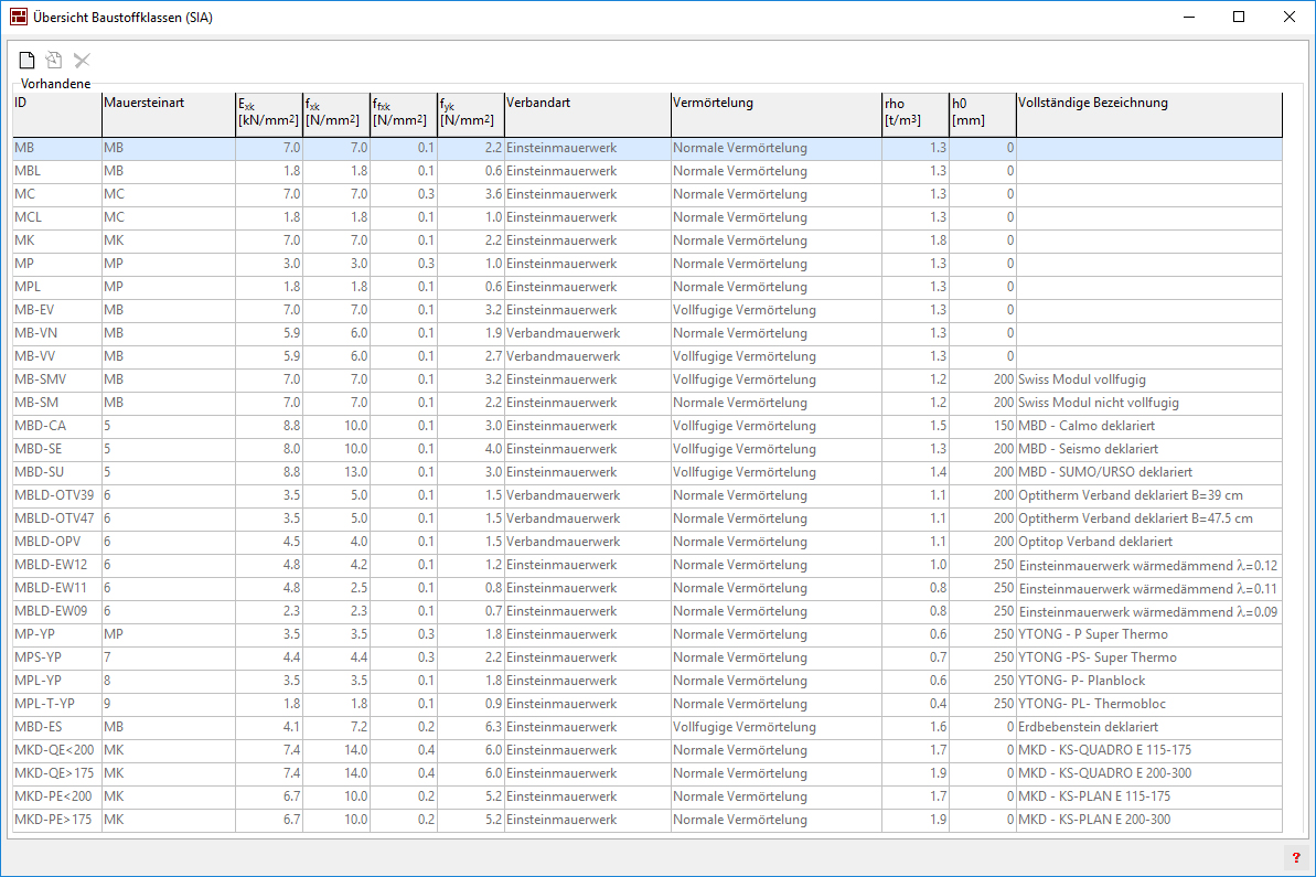
Types of masonryMURUS offers an extendable list of the established types of masonry with all the needed properties. |
|
|||||||||||||||
LoadingsAccording to the support type it is possible to specify a lateral excentricity for the normal force or a prescribed rotation at the top and/or bottom of a wall. |

|
|||||||||||||||
Verification of bearing capacityVerification of normal forceMURUS doesn't utilize the diagrams of the SIA266 code but rather carries out a nonlinear calculation based on the same moment-curvature characteristics used for creating the diagrams in the code and accounting for second order effects. This leaves more freedom in choosing the boundary conditions and eliminates interpolation inaccuracies. It furthermore yields the tnom for the verification of shear that otherwise has to be assumed to a conservative 1/4 of the thickness of the wall. Verification of shearThe procedure makes use of the tnom supplied by the preliminary verification of normal force. It then tries to find the stress fields for the verification of shear. The solution is not unique as long as the bearing capacity is not reached. Lateral loadsLateral loads are assumed to be transferred in vertical direction only. They are included in the calculation model for the verification of normal force and therefore act together with the normal forces. Carrying capacity
It is possible to evaluate the carrying capacity factor λ, by which a variable
loading |


|
|||||||||||||||
Verification of serviceabilityVerification of crack widths
The procedure starts with the calculation of the deformation of the
wall subjected to quasi permanent loads. If a state of equilibrium is found
the edge strains The calculation procedure allows to include lateral loads qz and thus respects also point 4.4.4 of the SIA266. Verification of shear
For the verification the claculative values of the interstory drift v and
the edge tension strain |

|
What was new in the former generations of MURUS
The collected changes compared to the predecessor generation are listed
here.
|